Aim:
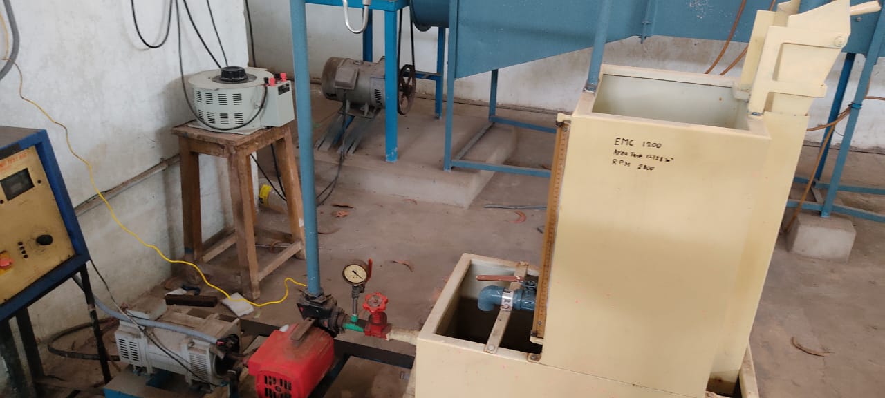
To study the performance characteristics of centrifugal pump test rig.
Apparatus:
1. Centrifugal pump test rig
2. Stopwatch
Formulae:
1. Actual discharge, `Q_{act}=\frac{AR}{T}` m3/sec
2.Pump input, `P_{i}=\frac{3600(n)}{EMC(t_{n})}` kW
3. Shaft power, `P_{s} = ` `mo t o r` `efficiency` X `P_{i}` kW
4. Pump output, `P_{o} = \gammaQH_{m}` kW
5. Pump efficiency, `\eta_{p}=(\frac{P_{o}}{P_{s}})` X `100`
6. Overall efficiency, `\eta_{o}=(\frac{P_{o}}{P_{i}})` X `100`
7. Specific speed, `N_{s}=\frac{N\sqrt{Q}}{H^{\frac{3}{4}}}`
where,
A = Cross-sectional area of the collecting tank in m2
R = Rise of water level in the collecting tank in m
T = Time taken for R m rise in the collecting tank in sec
n = Number of revolutions of energy meter disc
tn = Time taken for n revolutions in sec
EMC = Energy meter constant
γ = Specific weight of water = 9810 N/m3
Hm = Manometric head in m = Hs+Hd+Hf
Hs = Suction head in m = (Ps/1000)x13.6
Hd = Delivery head in m = 10xPd
Hf = Head loss due to friction in m
Ps = Suction pressure in mm of Hg
Pd = Delivery pressure in kg/cm2
N = Speed of the pump in r.p.m
Theory:
Centrifugal pump is a rotodynamic type of pump in which a dynamic pressure is developed which enables the lifting of liquids from a lower level to a higher level. The basic principle on which a centrifugal pump works is that when a certain mass of liquid is made to rotate by an external force, it is thrown away from the central axis of rotation and a centrifugal head is impressed which enbales it to rise to a higher level. Now if more liquid is constantly made available at the centre of rotation,a continous supply of liquid at a higher level may be ensured.
A centrifugal pump consists of a wheel or rotor called impeller which is provided with a series of backward curved blades or vanes, an air tight casing which surrounds the impeller, a suction pipe fitted with a foot valve anf strainer at the lower end and a delivery pipe provided with a delivery valve.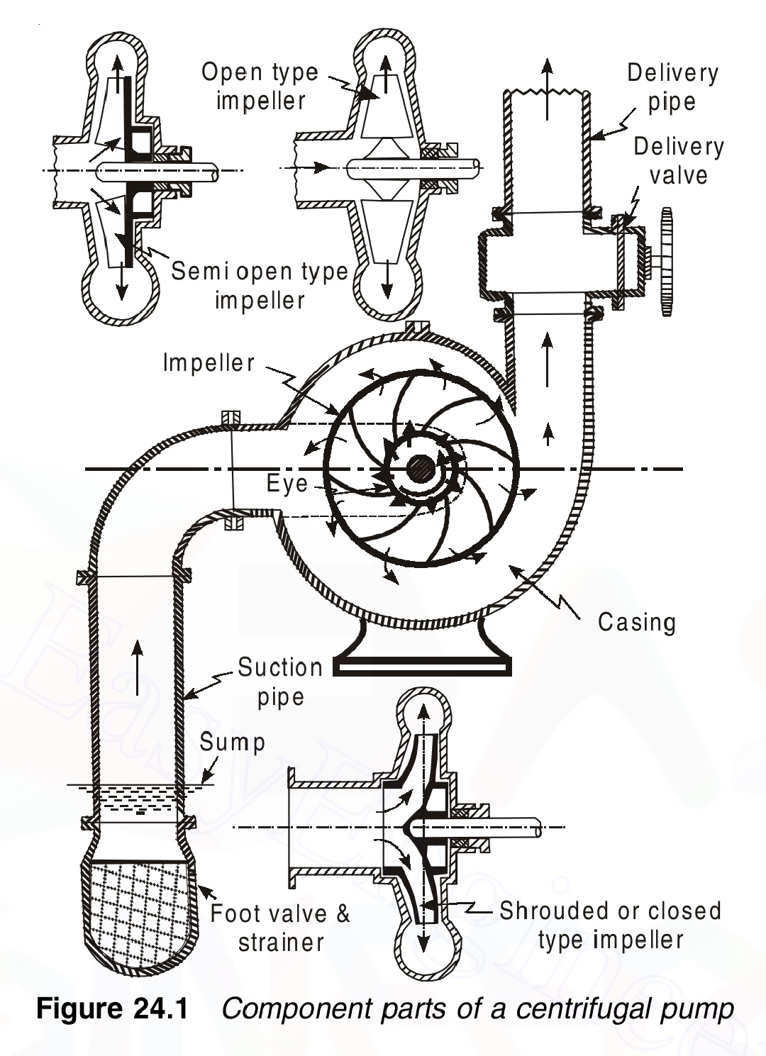 Working:
The centrifugal pump is initially primed wherein the suction pipe, casing of the pump and the portion of the delivery pipe up to the delivery valve are completely filled with the liquid to be pumped. With the delivery valve closed, the impeller is made to rotate. As a result a forced vortex is developed which imparts a centrifugal head to the liquid. Simultaneously the angular momentum is changed resulting in an increase of the liquid pressure. When the delivery valve is opened the liquid is forced to flow in an outward radial direction thereby leaving the vanes of the impeller at the outer circumference with high velocity and pressure. The high pressure of the liquid leaving the impeller enables the liquid to rise to a high level. This action is a continuous process because the eye of the impeller is continuously supplied with replacement liquid from the sump as a result of the pressure gradient in the suction pipe (a partial vacuum exists at the eye of the impeller and the liquid in the sump is at atmospheric pressure). The high absolute velocity at the outlet of the vanes is converted to useful pressure energy by shaping the casing such that the liquid flows through a gradually expanding passage.
Procedure:
1. Prime the pump, close the delivery valve and switch on the unit.(Priming means taking the air present in the suction and pressure pipes, volute casing by filling them with water. Ensure to close the aircock / priming adaptor as the air bubbles cease appearing and continous stream of water comes from aircock/ priming adaptor.)
2. Open the delivery valve and maintain the required delivery pressure. Note the delivery gauge pressure reading and the corresponding suction pressure gauge reading.
3. Close the drain valve of the collecting tank and record the time taken for 10 cm rise in the collectig tank.
4. Open the drain valve of collecting tank and record the time taken for 2 revolutions of the energy meter disc.
5. Repeat the above procedure for different delivery pressures by manipulating the delivery valve.
Observations:
Area of the collecting tank, A = .......... m2
Energy meter constant, EMC = .......... rev/kW-h
Speed of the pump, N = ........... r.p.m
Motor efficiency = .......... %
Table:
| SNo. |
Pd (kg/cm2) |
Ps (mm of Hg) |
T (sec) |
tn (sec) |
Hm (m) |
Q (m3/sec) |
Pi (kW) |
Ps (kW) |
Po (kW) |
ηp | ηo | Ns |
|---|---|---|---|---|---|---|---|---|---|---|---|---|
| 1 | ||||||||||||
| 2 | ||||||||||||
| 3 | ||||||||||||
| 4 | ||||||||||||
| 5 |
Graphs:
Graphs are plotted between,
a) Pi Vs Q
b) Po Vs Q
c) Hm Vs Q
d) ηo Vs Q 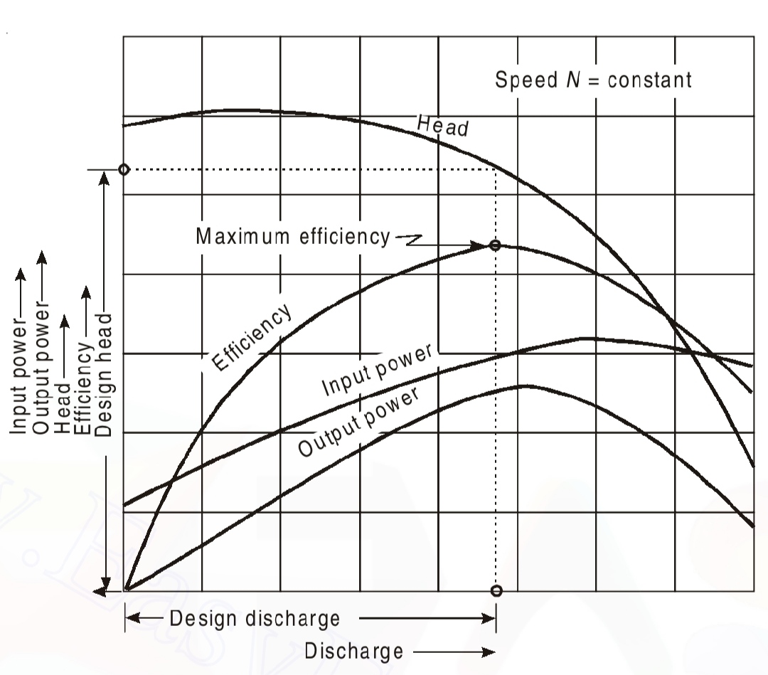
Precautions:
1. Check for the priming of the pump so that the air bubbles are not developed.(In the supplied apparatus a self- priming pump is used so the pump does not require priming.)
2. Sufficient time should be given for the flow to become steady uniform.
3. Apparatus should be in levelled condition.
4. Piezometric scale readings should be recorded at eye level.
Result:
The performance characteristics of centrifugal pump have been studied and the
a) Overall efficiency of the pump, ηo = .......... %
b) Specific speed of the pump, Ns = ..........