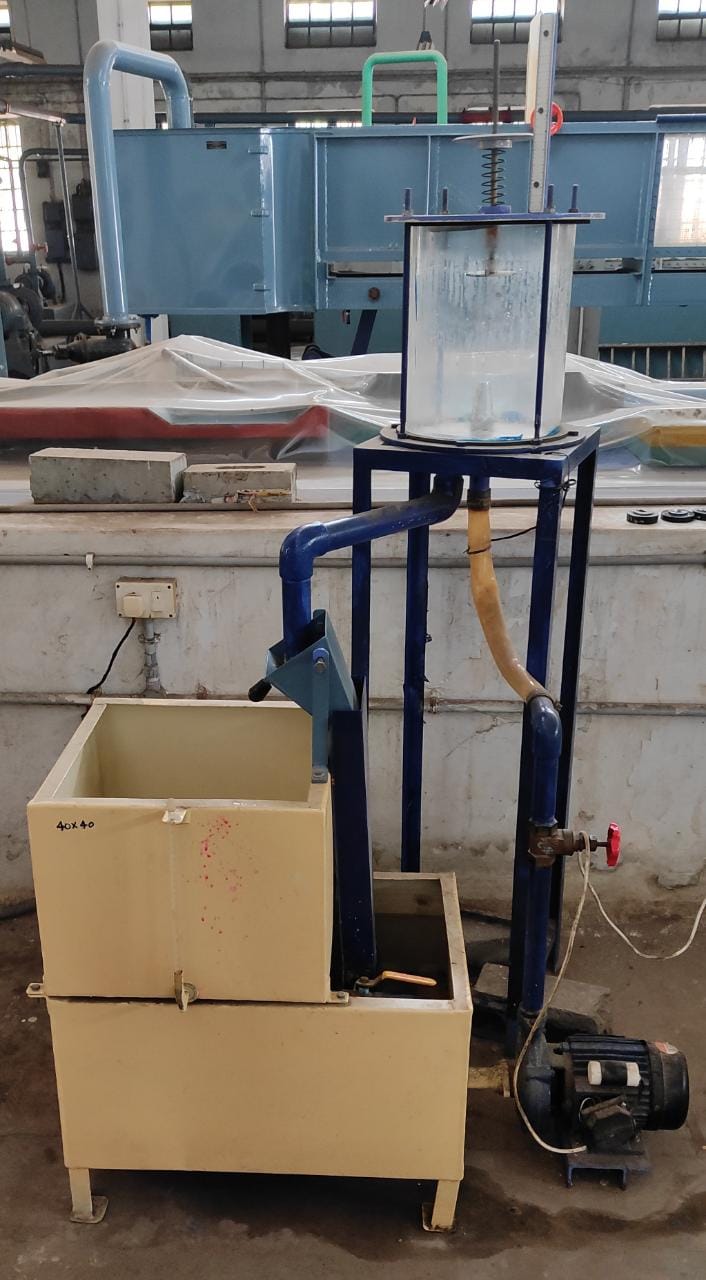
Aim:
To determine coefficient of impact of jet on flat and hemispherical vanes.
Apparatus:
1. Impact of jet apparatus equipped with flat vane
2. Impact of jet apparatus equipped with hemispherical vane
3. Dead weights
4. Stopwatch
Formulae:
1. Actual discharge, `Q = \frac{AR}{T}` m3/sec
2. Velocity of the jet, `v = \frac{Q}{a}` m/sec
3. Theoritical force exerted by the jet,
1) `F_{th} = \rhoav^{2}` N (for flat vane)
2) `F_{th} = \2rhoav^{2}` N (for hemispherical vane)
4. Actual force exerted by the jet, `F_{act}= 9.81W` N
5. Coefficient of impact, `C_{i}= \frac{F_{act}}{F_{theo}}`
where,
A = Area of the collecting tank insq-m
R = Rise of water level in collecting tank in m
T = Time taken for R m rise of water level in sec
a = Cross-sectional area of the nozzle in sq-m `= \frac{\pi D^{2}}{4}`
d = Diameter of the nozzle in m
Ρ = Density of water = 1000 kg/m3
W = Cummulative weight placed on the weight pan in kg
Theory:
Momentum equation is based on Newton's second law of motion which states that the algebraic sum of external forces applied to control volume of fluid in any direction is equals to the rate of change of momentum in that direction. The external forces includes the components of the weights of the fluid and of the forces exerted externally upon the boundary surface of the control volume.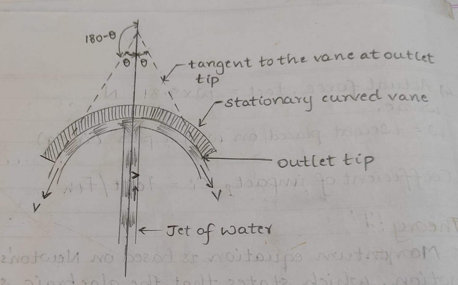
If a vertical jet moving with a velocity ‘v’ is made to strike a target, which is free to move in vertical direction, then a force will be exerted on the target by the impact of jet. According to momentum equation, this force (which is also equal to the force required to bring back the target to its original position) must be equals to rate of change of momentum of the jet flow in that direction.
Let a vertical jet of cross-sectional area ‘a’ and velocity ‘V’ be striking a smooth symmetrical curved vane at its center on the concave side. After striking the vane the jet will divide itself and will leave the vane at its both the ends. The vane being smooth, the velocity of the leaving jets will be ‘V’.
Let ‘2α’ be the angle between the two tangents drawn to the vein at its outlet tips. Thus the jet after striking will be deflected on each side through the angle of (180 - α). Accordingly the component of the velocity of the leaving jet in the direction of flow of incoming jet is’-Vcosα’.
Therefore,the application of the impluse – momentum equation gives the force exerted on the plate in the direction of flow of jet as,
F= 𝜌aV(V-(-vcosα))
F= 𝜌aV2(1+cosα)
For α=90° i.e., flat vane,
F= 𝜌aV2
For α=180° i.e., hemispherical vane,
F= 2𝜌aV2
Procedure:
1. Note down the cross-sectional details of collecting tank (length,width) and of nozzle(diameter).
2. Note down the position of the upper disc (or the weights pan) when the jet is not running.
3. The water supply is admitted to the nozzle and as the jet strikes the vane, the position of the upper disc is changed.
4. Place the weight on the upper disc and bring back the upper disc to its original position by regulating the flow.
5. At this position,find out the discharge by diverting the flow into the collecting tank.
6. Note down the time required for 5 cm rise of water level in the collecting tank. Drain out the water present in the collecting tank by stopping the inflow to the collecting tank.
7. Repeat the procedure by placing subsequent weights available on to the upper disc.
Observations:
Diameter of the nozzle, d = .......... m
Cross-sectional area of the collecting tank, A = .......... m2
Table(Flat vane):
| SNo. |
Weight placed on upper disc (kg) |
W (kg) |
R (m) |
T (sec) |
Q (m3/sec) |
v (m/sec) |
Fth (N) |
Fact (N) |
Ci |
|---|---|---|---|---|---|---|---|---|---|
| 1 | |||||||||
| 2 | |||||||||
| 3 | |||||||||
| 4 | |||||||||
| 5 |
Table(Hemispherical vane):
| SNo. |
Weight placed on upper disc (kg) |
W (kg) |
R (m) |
T (sec) |
Q (m3/sec) |
v (m/sec) |
Fth (N) |
Fact (N) |
Ci |
|---|---|---|---|---|---|---|---|---|---|
| 1 | |||||||||
| 2 | |||||||||
| 3 | |||||||||
| 4 | |||||||||
| 5 |
Graphs:
1. Fact Vs Fth: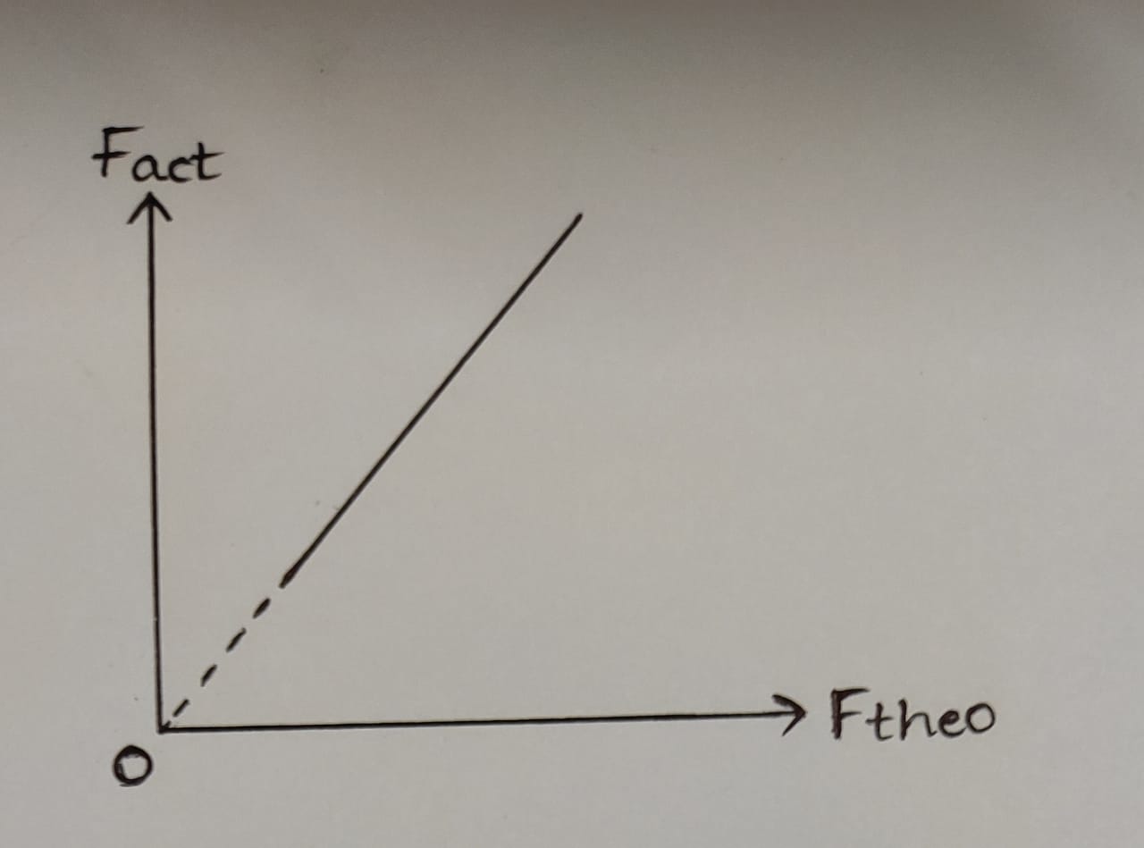
2. Fact Vs ` \frac{v^{2}}{2g}`: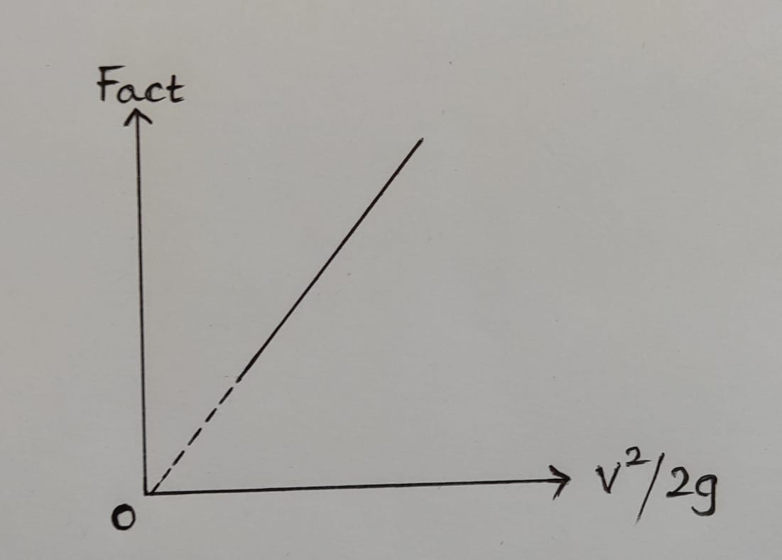
3. Fact Vs v:
Precautions:
1. Apparatus should be in levelled condition.
2. Discharge through nozzle should be varied gradually with help of flow valve.
2. Piezometric scale readings should be recorded at eye level.
3. Drain valve of the collecting tank should be closed before admitting water in to the collecting tank.
4. It is advisable to lower the weightpan(along with the dead weights) from higher position to lower position by regulating the flow valve.
Result:
1. Coefficient of impact of flat vane(Ci),
Average of tabulated values = ..........
From Fact Vs v graph = ..........
From Fact Vs ` \frac{v^{2}}{2g}` graph = ...........
From Fact Vs Fth graph = ..........
2. Coefficient of impact of hemispherical vane(Ci),
Average of tabulated values = ...........
From Fact Vs v graph = ..........
From Fact Vs ` \frac{v^{2}}{2g}` graph = ...........
From Fact Vs Fth graph = ...........