Aim:
To determine the coefficient of discharge of nozzle meter.
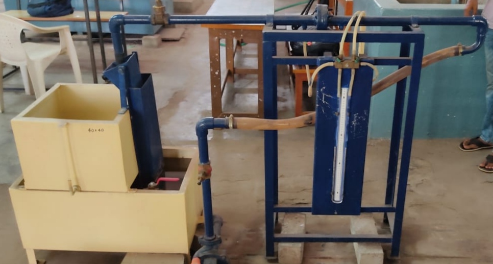
Experimental setup:
The experimental set up consists of a circuit through which the water is circulated continuously. The circuit is having a pipe-line of 25 mm diameter connected with a nozzle meter. Nozzle meter is having a d/D =0.6 and is provided with two pressure tappings one at upstream and other at downstream side. A U tube differential manometer is provided to measure the pressure difference between two sections of nozzle meter. A regulating valve is provided on the downstream side of pipe to regulate the flow. A collecting tank is used to find the actual discharge through the circuit.
Formulae:
1. Actual discharge, `Q_{act}=\frac{AR}{T}` cm3/sec
2. Theoritical discharge, `Q_{th}=\frac{a_{1}a_{2}\sqrt{2gH}}{\sqrt{a_{1}^{2}-a_{2}^{2}}}` cm3/sec
3. Coefficient of discharge, `C_{d}=\frac{Q_{act}}{Q_{th}}`
where,
A = Cross sectional area of the collecting tank in cm2
R = Rise in the level of water in collecting tank in cm
T = Time taken for R cm rise in collecting tank
g = Acceleration due to gravity = 980 cm/sec2
a1 = Cross-sectional area of the pipeline in m2 = `\frac{\pi d_{1}^{2}}{4}`
a2 = Cross-sectional area of nozzle in m2 = `\frac{\pi d_{2}^{2}}{4}`
d1 = Diameter of the pipeline in m
d2 = Diameter of the nozzle in m
h = Difference in manometer limb readings in cm of water = 12.6(hm)
hm = Difference in manometer limb readings in cm of mercury = h1 - h2
h1 = Left limb manometer reading in cm of mercury
h2 = Right limb manometer reading in cm of mercury
Theory:
Nozzlemeter is a device used for measurement of rate of flow of fluid through a pipe. The basic principle on which Nozzlemeter works is that by reducing the cross-sectional area of flow passage, a pressure difference is created and the measurement of the pressure difference enables the determination of the discharge through the pipe.
The flow nozzle is a device for measuring discharge through pipes is nothing but a venturi meter without its diverging cone. It differs from an orifice meter in the sense that it is made curved so that the jet contraction is not so large as in orificemeter. Therefore, it is sometimes called as long radius nozzle.
In a nozzle, the fluid is guided smoothly to the section of minimum area of stream and also it has no sharp edges and hence the nozzle has a considerably higher discharge coefficient than the orifice plate. Nozzle is better suited for flow measurements when the fluid is likely to contain dust particles.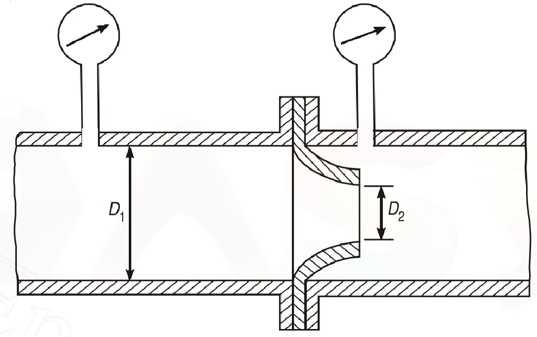
The expression for the discharge computation in a flow nozzle is on the same pattern as on venturi meter and orifice meter. The discharge coefficient can be calculated using formula,
`Q=\frac{C_{d}a_{1}a_{2}\sqrt{2gH}}{\sqrt{a_{1}^{2}-a_{2}^{2}}}`
Where,
Cd is coefficient of nozzle meter
a1 is cross- sectional area of nozzle
a2 is cross –sectional area of pipe
g is the acceleration due to the gravity
h is the difference of head in terms of water.
Procedure:
1. Note down the relevant dimensions, such as the diameter of the pipe, the diameter of the throat, the area of the collecting tank, etc.
2. The regulating valve of a pipe line is kept open.
3. The pressure taps of a nozzle meter are kept open.
4. Open the inlet flow control valve and regulate the valve to allow a steady flow through the pipe. Check if there is any air in the manometer tube. If so, remove it.
5. The flow rate was adjusted to its maximum value. By maintaining a suitable amount of steady flow or near steady flow in the pipe circuit, there is a steady, non-uniform flow in the circuit. Time is allowed to stabilise the levels in the manometer tube.
6. The discharge flowing in the circuit is recorded together with the water levels in the left and right limbs of the manometer tube.
7. The flow rate is reduced in stages by means of a flow control valve, and the discharge and readings of the manometer are recorded for every stage.
Observations:
Cross sectional area of the collecting tank, A = .......... cm2
Rise in the level of water in the collecting tank, R = ........... cm
Diameter of the pipe, d1 = .......... cm
Diameter of the nozzle, d2 = .......... cm
Table:
| SNo. |
h1 (cm) |
h2 (cm) |
T (sec) |
hm (cm) |
h (cm) |
Qth (cm3/sec) |
Qact (cm3/sec) |
Cd |
|---|---|---|---|---|---|---|---|---|
| 1 | ||||||||
| 2 | ||||||||
| 3 | ||||||||
| 4 | ||||||||
| 5 |
Graphs:
1. Q Vs H: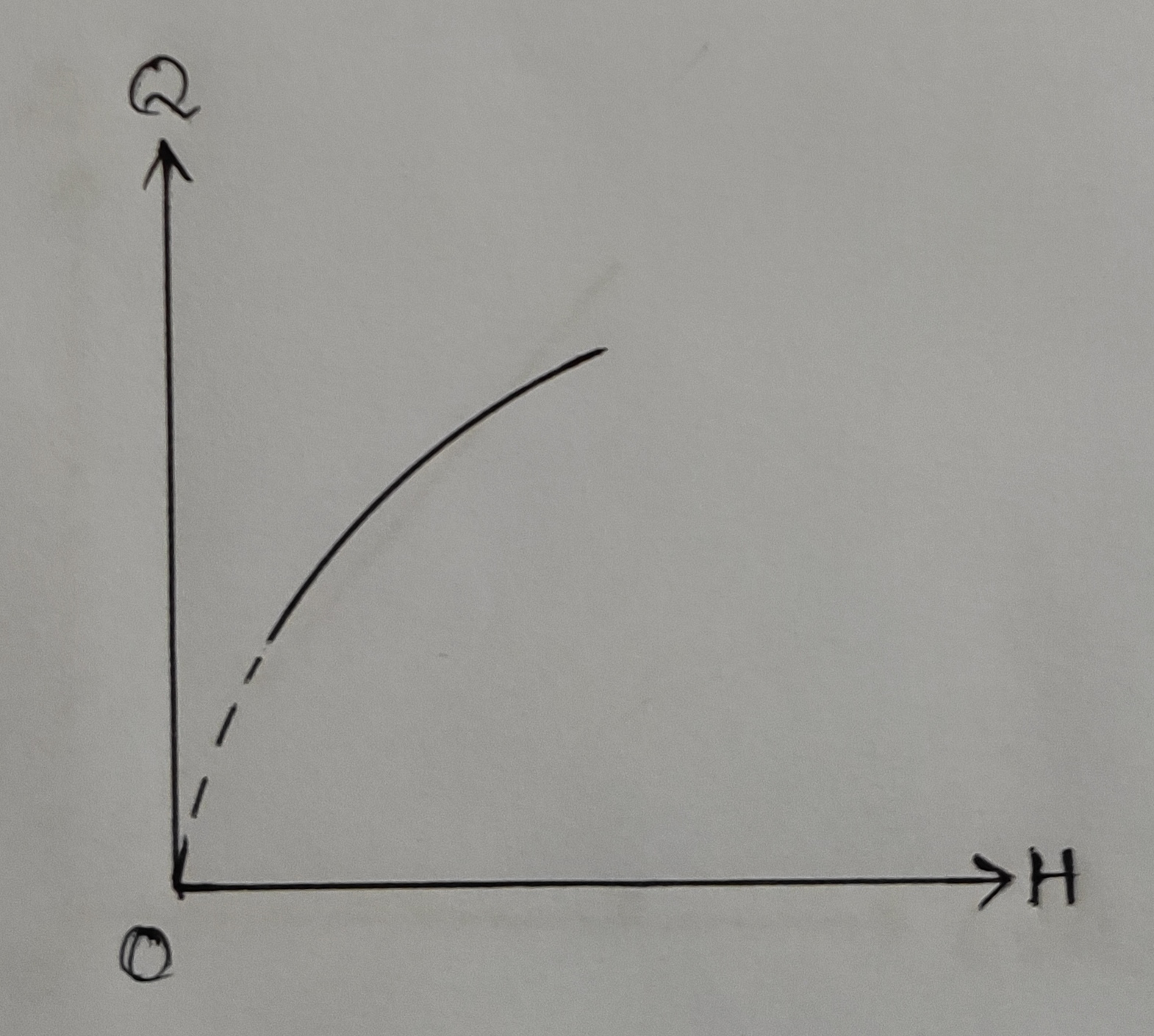
2. Log Q Vs log H: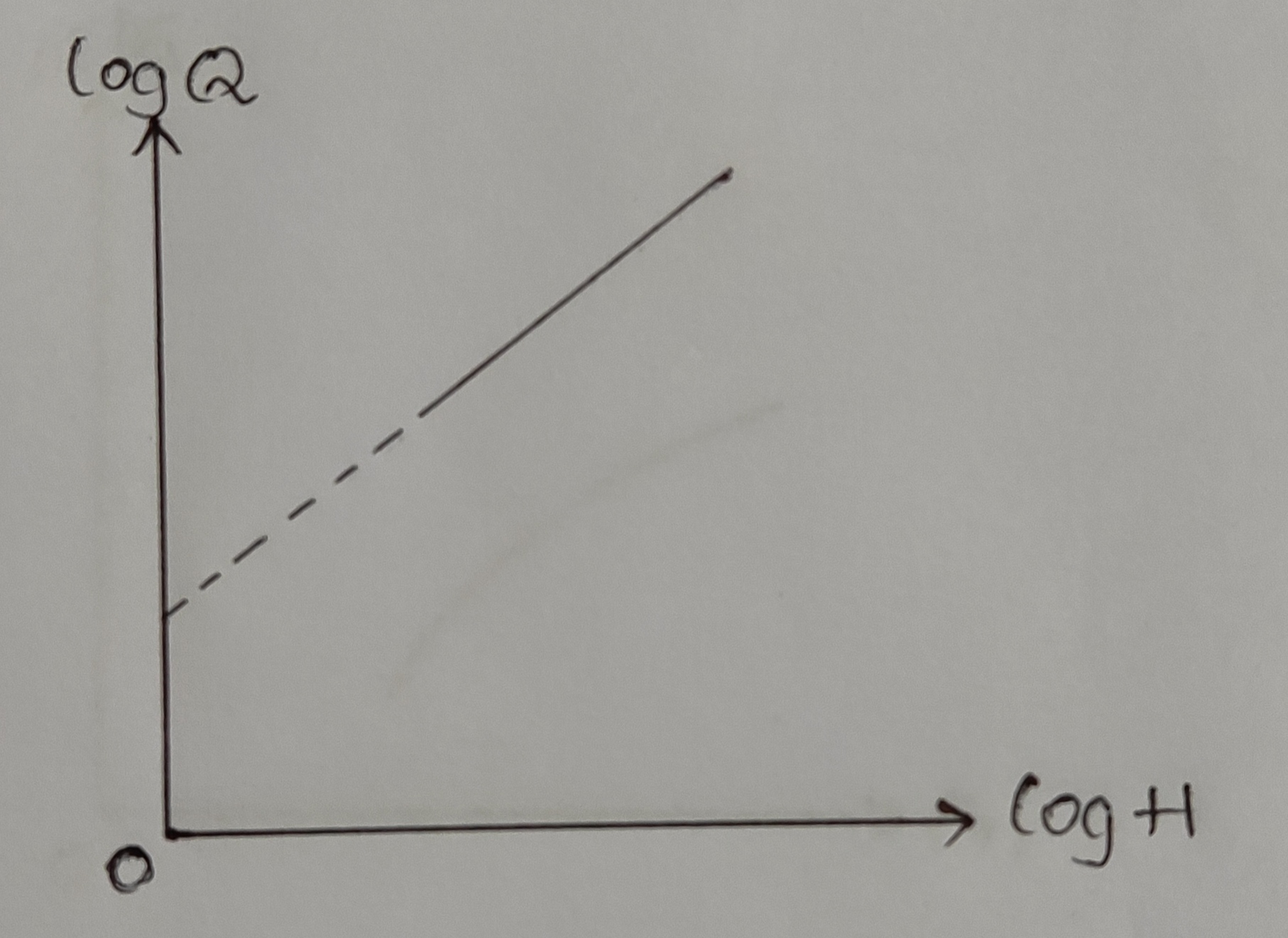
3. Q vs `\sqrt{H}`: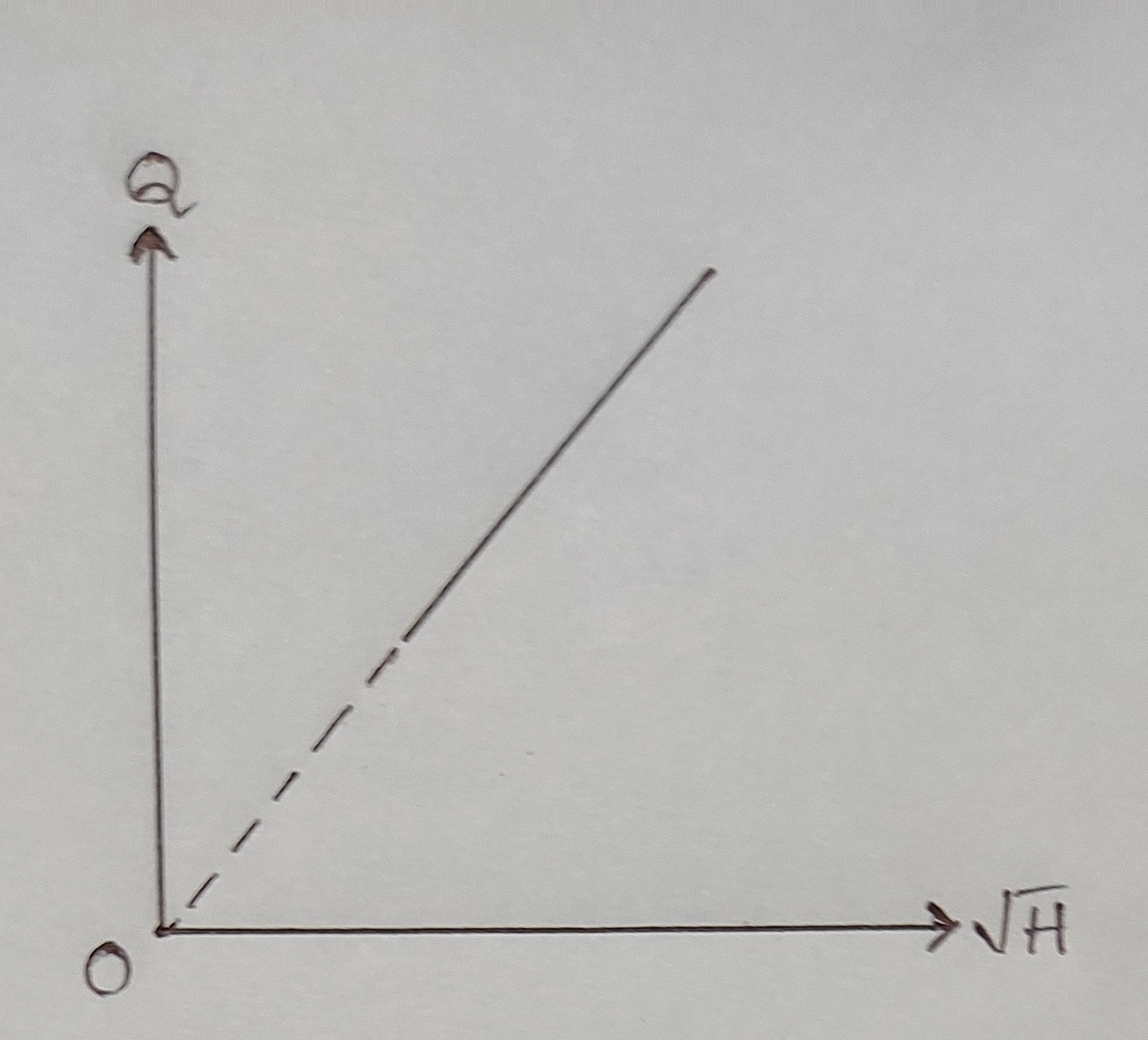
Precautions:
1. Remove all entrapped air from two limbs of manometer.
2. Maintain constant discharge for one set.
3. Piezometric scale readings should be recorded at eye level.
Result:
Coefficient of discharge of nozzle meter,
a) From average of calculated values, Cd = ..........
b) From Qact Vs H graph, Cd = ..........
c) From Qact Vs `\sqrt{H}` graph, Cd = ..........
d) From log Qact Vs log H graph, Cd = ..........