Aim:
To determine the Darcy- Weisbach’s friction factor for flow through pipes of different sizes.
Apparatus:
1. Pipe Friction apparatus
2. Stopwatch
Formulae:
1. Friction factor, `f = \frac{2gDh_{f}}{lv^{2}}`
where,
g = Acceleration due to gravity = 9.8 m/sec2
D = Diameter of the pipe in m
l = Length of the pipe in m
hf = Head loss due to friction in m of water =12.6*x
x = Difference in the level of mercury in the limbs of a manometer in m of Hg = `\frac{L-R}{100}`
L = Left limb reading of manometer in cm of Hg
R = Right limb reading of manometer in cm of Hg
v= Mean velocity of the flow in pipe in m/sec = `v = \frac{Q_{act}}{a}`
a = cross-sectional area of pipe in m2` = \frac{\pi D^{2}}{4}`
Qact = Actual discharge in m3/sec ` = \frac{AR}{T}`
A = Cross-sectional area of the collecting tank in m2
T = Time taken for R m rise in the tank in sec
Theory:
When liquid flows through a pipe under pressure, some head is lost in overcoming the friction between the pipe wall and the flowing fluid. Head loss due to friction is important from an engineering point of view as the design of pipe mains carrying water from any reservoir to a township over a long distance mainly depends upon friction factor. 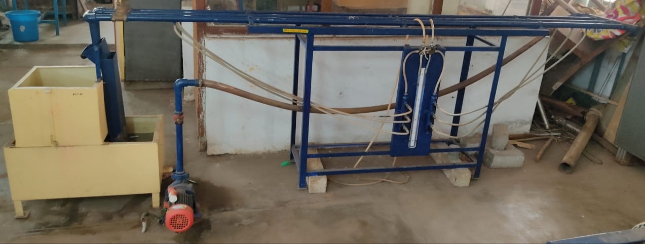
Consider a horizontal pipe of cross-sectional area A carrying a fluid with a mean velocity V. Let 1 and 2 be the two sections of pipe L distance apart, where the intensities of pressure be p1 and p2 respectively. By applying Bernoulli’s equation between sections 1 and 2, we obtain
`\frac{P_{1}}{\gamma}+\frac{V_{1}^{2}}{2g}+z_{1}=\frac{P_{2}}{\gamma}+\frac{V_{2}^{2}}{2g}+z_{2}+h_{f}`
Since, V1 = V2 and z1 = z2
Loss of head, `h_{f}=\frac{p_{1}-p_{2}}{\gamma}`
Let f’ be the frictional resistance per unit area at unit velocity, then frictional resistance
= f’ * area * Vn
= f’ * PL * Vn
where,
P = Wetted perimeter of the pipe
The pressure forces at the sections 1 and 2 are p1A and p2A respectively. Thus resolving all the forces horizontally, we have
p1A = p2A + frictional resistance
(p1-p2) A= f’ * PL* Vn
(p1 - p2) = f’ * (P/A) * L * Vn
But,
`h_{f}=\frac{p_{1}-p_{2}}{\gamma}`
`h_{f}=\frac{f'}{\gamma}\frac{P}{A}LV^{n}`
`h_{f}=\frac{f'}{\gamma}\frac{LV^{n}}{m}`
where,
m = Hydraulic mean depth = `\frac{A}{P}`
For pipes running full,
`m = \frac{A}{P} = \frac{\frac{\pi D^{2}}{4}}{\piD}=\frac{D}{4}`
Now,
`h_{f} = \frac{4f'}{\gamma}\frac{LV^{n}}{D}`
Assuming n = 2 and putting ` \frac{4f'}{\gamma}=\frac{f}{2g}`,
` h_{f}=\frac{fLV^{2}}{2gD}`
Procedure:
1. Note down the diameter of the pipe, length of pipe between pressure tappings and area of the collecting tank.
2. Pressure tappings of the pipe being tested are kept open while for the other pipes they are kept closed.
3. Open the inlet flow control valve and regulate the valve to allow a steady flow through the pipe.
4. The flow rate is initially adjusted to its maximum value by completely opening the flow control valve. Time is allowed to stabilize the levels in manometer tube.
5. The discharge flowing through the pipe is measured by recording the time required to collect certain volume of fluid in the collecting tank. Also, record the corresponding mercury manometer readings.
6. The flow rate is reduced in stages by means of flow control valve and the corresponding discharge & manometer readings are noted.
7. Repeat the procedure for different sets of pipes available in the pipe friction apparatus.
Observations:
Length of the pipe, L = .......... m
Cross - sectional area of the collecting tank, A = .......... m2
Diameter of the pipe, D = .......... m
Table:
| SNo. |
L (cm of Hg) |
R (cm of Hg) |
x (m of Hg) |
hf (m of water) |
R (m) |
T (sec) |
Qact (m3/sec) |
v (m/sec) |
f | v2/2g | log hf | log v |
|---|---|---|---|---|---|---|---|---|---|---|---|---|
| 1 | ||||||||||||
| 2 | ||||||||||||
| 3 | ||||||||||||
| 4 | ||||||||||||
| 5 |
Graphs:
1. hf Vs v: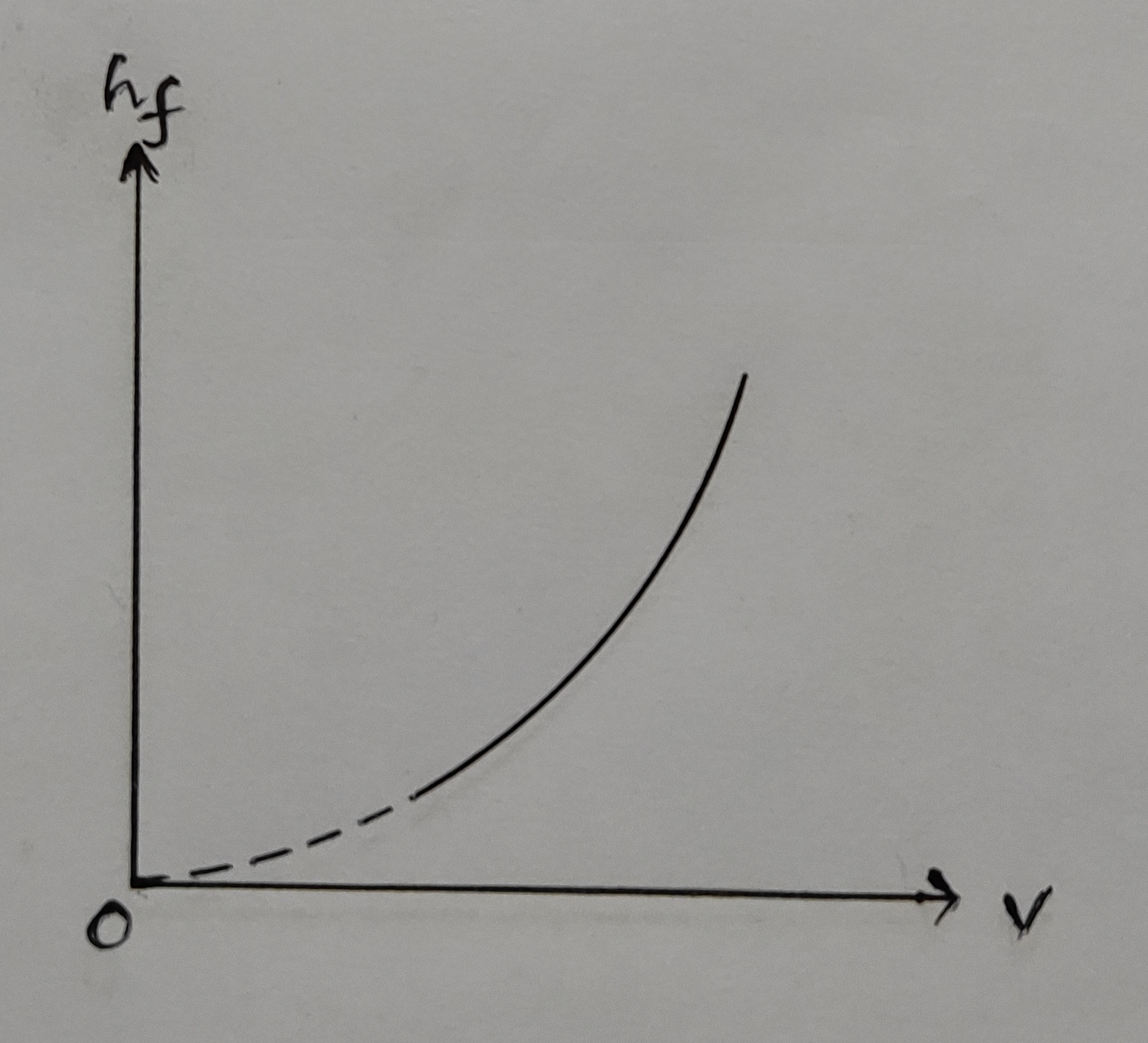
2. hf Vs `\frac{v^{2}}{2g}`: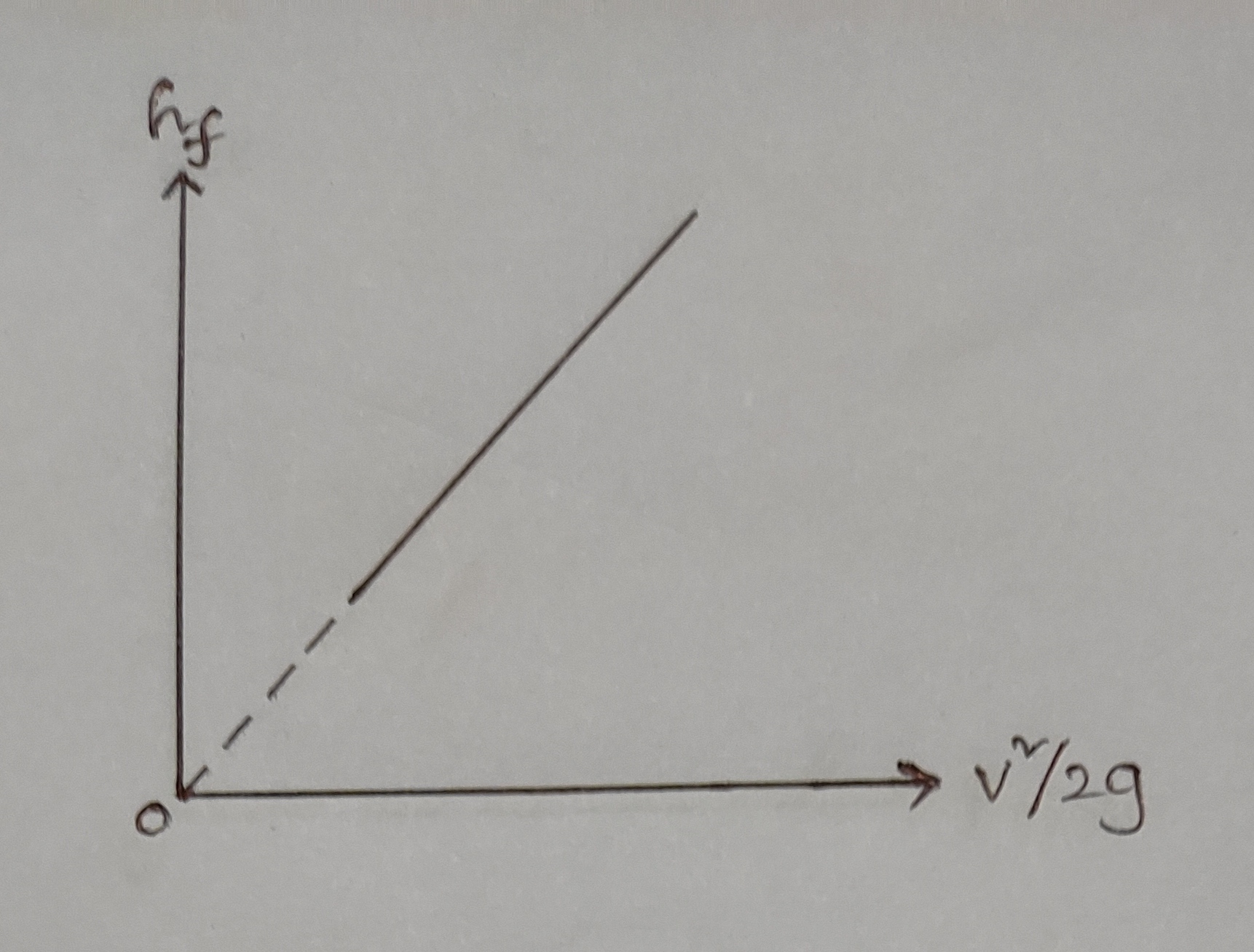
3. log hf Vs log v: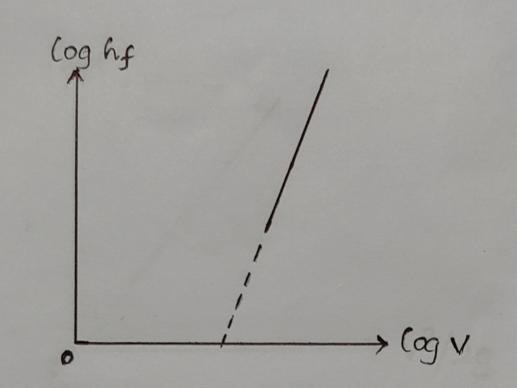
Precautions:
1. Sufficient time should be given for the flow to become steady-uniform.
2. Remove the entrapped air in manometer tubes. This can be achieved by opening the valves provided at the top of the manometer simultaneously. If they are opened out separately, the manometric fluid will spill out.
3. Apparatus should be in levelled condition.
Result:
1. Friction factor of the half-inch pipe,
a) Average of tabulated values = ..........
b) From hf Vs `\frac{v^{2}}{2g}` graph = ..........
c) From hf Vs v graph = ..........
d) From log hf Vs log V graph = ..........
2. Friction factor of the three fourth-inch pipe,
a) Average of tabulated values = ..........
b) From hf Vs `\frac{v^{2}}{2g}` graph = ..........
c) From hf Vs v graph = ..........
d) From log hf Vs log V graph = ..........