Aim:
To determine the coefficient of discharge of a small orifice by two methods,
a) Constant head method
b) Falling head method
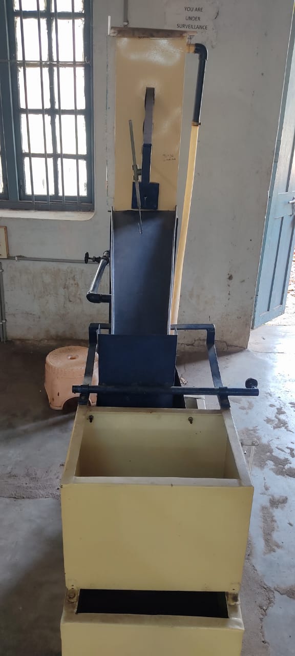
Experimental setup:
The experimental set-up consists of a supply tank with an overflow arrangement and a gauge glass tube for water level measurement in the tank. There is also provision for fixing the various orifices (interchangeable) installed in the vertical plane of the tank side. A set of orifices consisting of 10 mm and 15mm diameter orifices is provided with the apparatus. The arrangement is made such that the water passes only through this attached opening. Water comes out of the opening in the form of a jet.
A horizontal scale on which a vertical scale is mounted with a hook gauge is attached to the supply tank. Thus, hook gauge can be moved horizontally as well as vertically in the x and y directions and its corresponding movement can be read on the horizontal scale and vertical scale respectively. A collecting tank is used to determine the actual discharge of water through the jet.
Formulae:
Constant head method:
1. Actual discharge, `Q_{a} = \frac{A_{c}R}{T}` cm3/sec
2. Theoritical discharge, `Q_{th} = a\sqrt{2gH}` cm3/sec
3. Coefficient of discharge, `C_{d} = \frac{Q_{a}}{Q_{th}}`
where,
Ac = Cross sectional area of the collecting tank in cm2
R = Rise in level of water in collecting tank in cm
T = Time taken for R cm rise in the collecting tank
a = Cross sectional area of the orifice in cm,2 = `\frac{\pi d^{2}}{4}`
d = Diameter of the orifice in cm
g = Acceleration due to gravity = 980 cm/sec2
H = Constant head of water maintained in the balancing tank in cm
Variable head method:
Coefficient of discharge, `C_{d} = \frac{2A(\sqrt{H_{1}}-\sqrt{H_{2}})}{t a \sqrt{2g}}`
where,
H1 = initial head of water above the centre of the orifice
H2 = final head of water above the centre of the orifice
t = time taken by water to fall from H1 to H2
a = cross-section area of the orifice
A= cross-section area of the balancing tank
Theory:
• Orifices are openings in the wall or bottom of a tank to discharge the fluid from the tank.
• Orifices are usually round, though square, triangular, and rectangular ones are not unusual.
• The orifice will act as a “small orifice” when the head of water in the orifice tank is greater than five times the diameter of the orifice.
• The coefficient of discharge through an orifice can be obtained by two different methods, namely the constant head method and the falling head method.
1) Coefficient of discharge by the constant head method: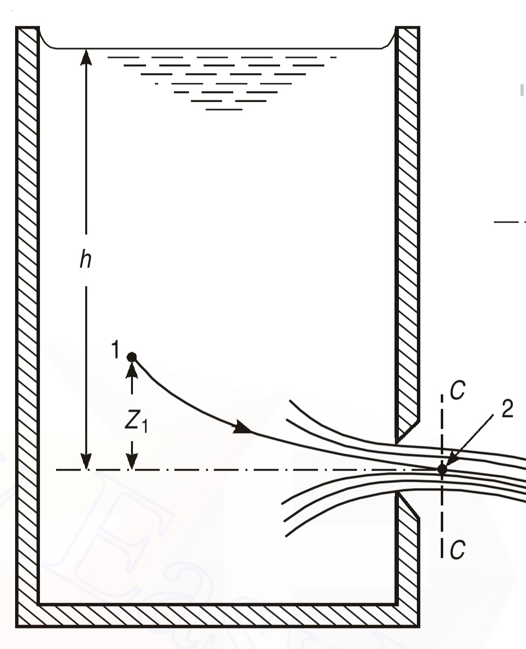
As the head ‘H’ on the orifice is held constant, the application of Bernoulli’s equation between the free surface and center of the orifice yields `v = \sqrt{2gH}` which is also known as Torricelli’s formula.
If ‘a’ is the area of the cross-section of the orifice, the discharge ‘Q’ is given by,
`Q_{th} = a\sqrt{2gH}`
Where,
‘H’ is the head of water above the center of the orifice.
The actual discharge Qa is obtained from collecting tank observations
`Q_{a} = \frac{A_{c}R}{T}`
Where,
‘Ac’ is cross-sectional area of collecting tank
‘R’ is rise of water
'T' is time taken for ‘R’ rise of water in collecting tank
Hence,
`C_{d} = \frac{Q_{a}}{Q_{th}}`
2) Coefficient of discharge by the falling head method: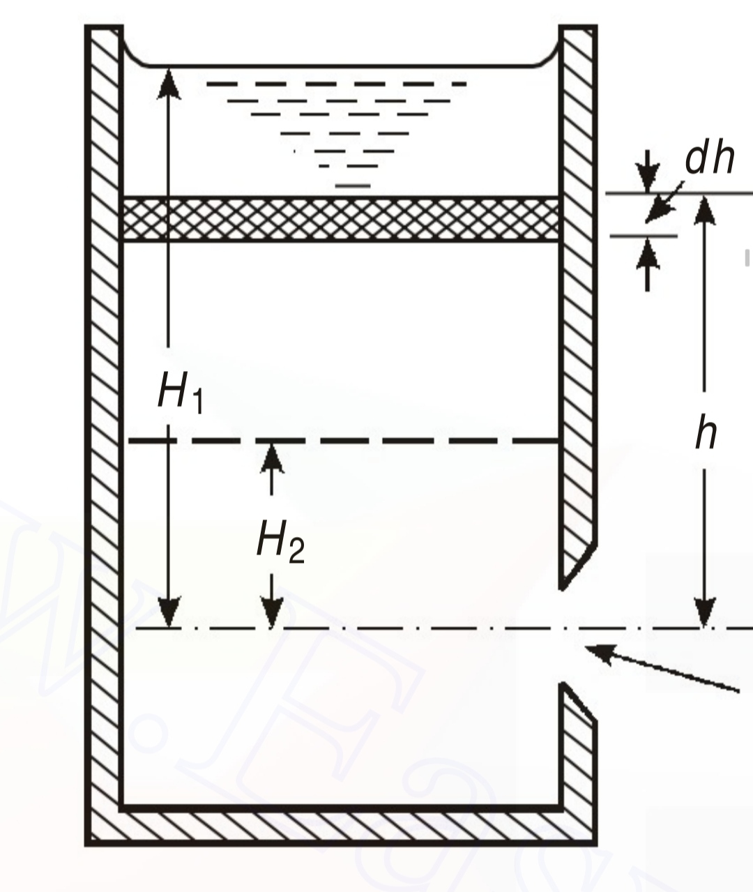
As the name of the method itself indicates, the head is not held constant, but is allowed to fall from H1 to H2, under these conditions, the coefficient of discharge is given by,
`C_{d} = \frac{2A(\sqrt{H_{1}}-\sqrt{H_{2}})}{t a \sqrt{2g}}`
Where,
H1 = initial head of water above the centre of the orifice
H2 = final head of water above the centre of the orifice
t = time taken by water to fall from H1 to H2
a = cross-section area of the orifice
A= cross-section area of the balancing tank
Procedure:
A. CONSTANT HEAD METHOD:
1) Open the inlet valve, and it has to be adjusted such that the head above the orifice remains constant.
2) Note the head of the water above the center of the orifice.
3) Collect ‘R’ cms of water in the collecting tank, and note the time of collection ‘t’ sec, and drain off the water in the collecting tank.
4) Increase the rate of discharge by adjusting the gate valve, and repeat steps 2 and 3 atleast five times more.
B. FALLING HEAD METHOD:
1) Open the inlet valve and allow sufficient head to build up, then close the inlet valve.
2) Decide the values of H1 and H2 and find the time taken ‘t’ in bringing down the water level in the tank from H1 to H2.
3) Repeat steps 1 and 2 for five more different combinations of H1 and H2.
Observations:
Constant head method:
Diameter of the orifice, d = .......... cm
Cross sectional area of the collecting tank, Ac = .......... cm2
Rise in the level of water in the collecting tank, R = .......... cm
Table:
| SNo. |
H (cm) |
T (sec) |
Qth (cm3/sec) |
Qa (cm3/sec) |
Cd |
|---|---|---|---|---|---|
| 1 | |||||
| 2 | |||||
| 3 | |||||
| 4 | |||||
| 5 |
Variable head method:
Cross sectional area of the balancing tank, A = .......... cm2
Diameter of the orifice, d = .......... cm
Table:
| SNo. |
H1 (cm) |
H2 (cm) |
t (sec) |
Cd |
|---|---|---|---|---|
| 1 | ||||
| 2 | ||||
| 3 | ||||
| 4 | ||||
| 5 |
Graphs:
CONSTANT HEAD METHOD:
1. Q Vs H: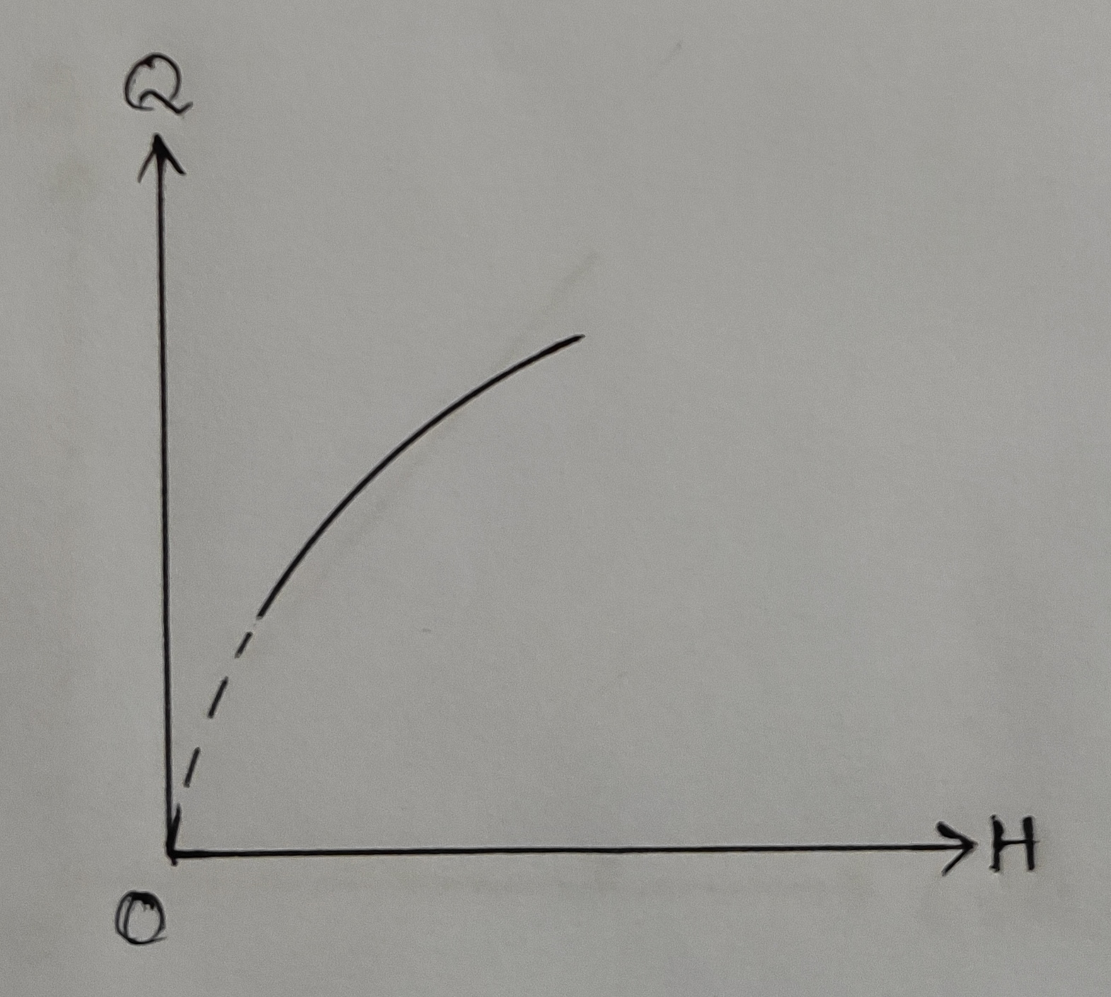
2. Log Q Vs log H: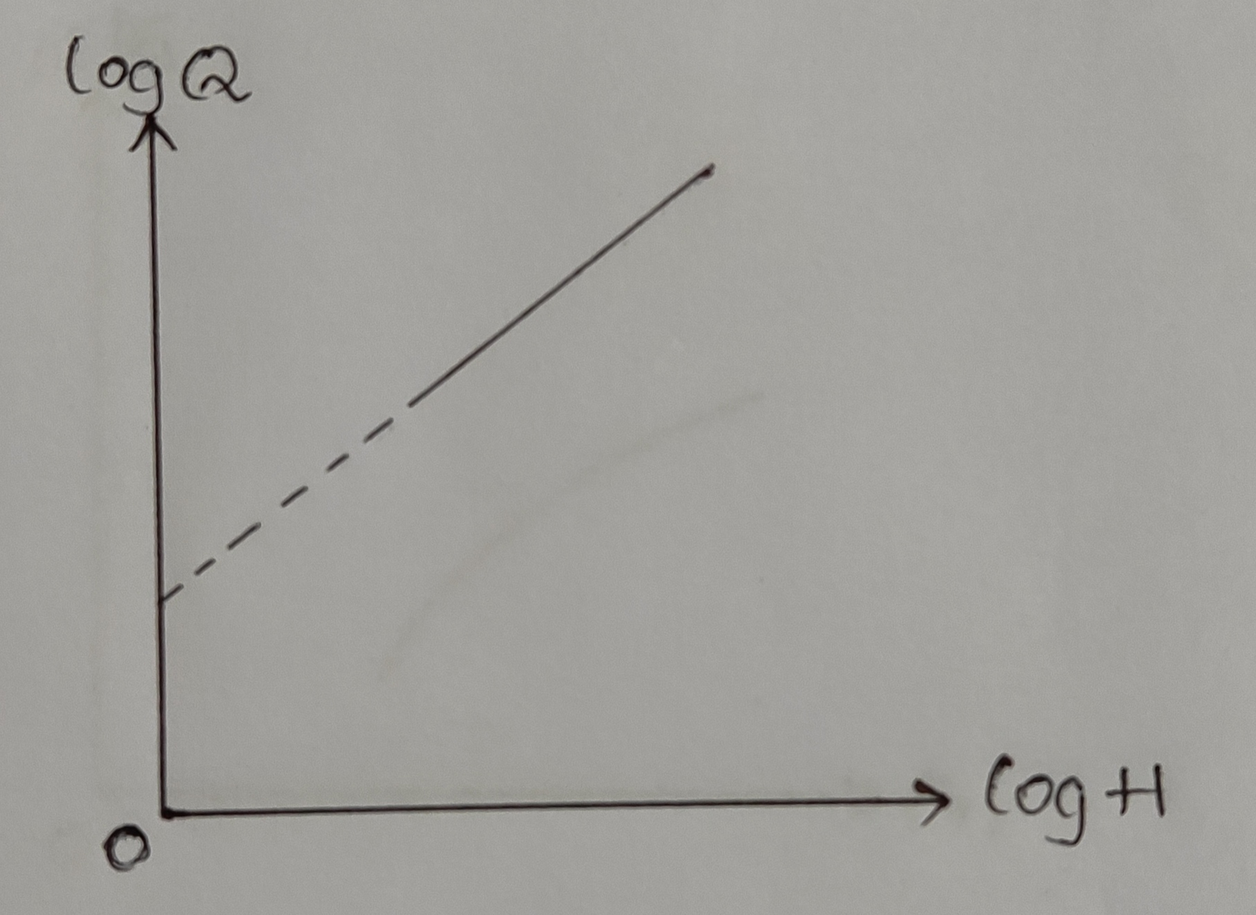
3. Q vs `\sqrt{H}`: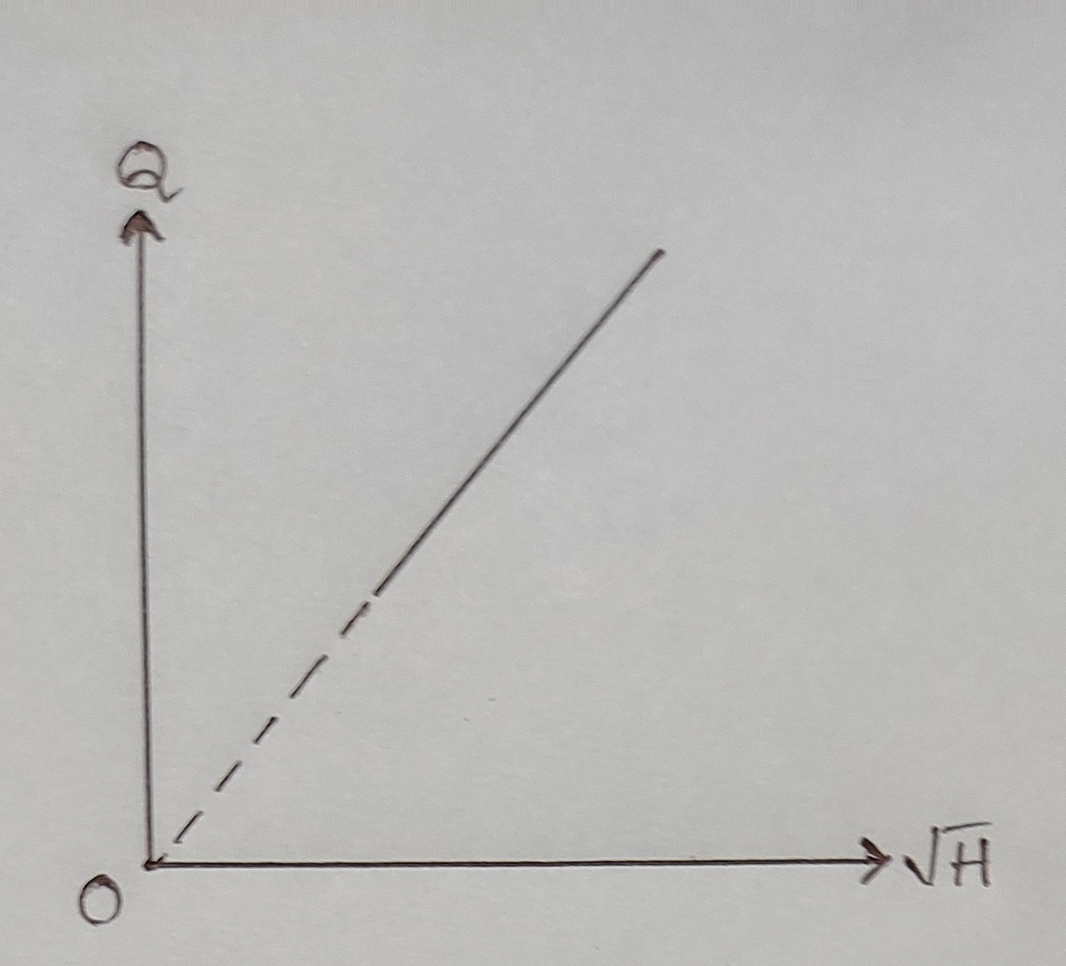
VARIABLE HEAD METHOD:
1. Q Vs `\sqrt{H_{1}}- \sqrt{H_{2}}`: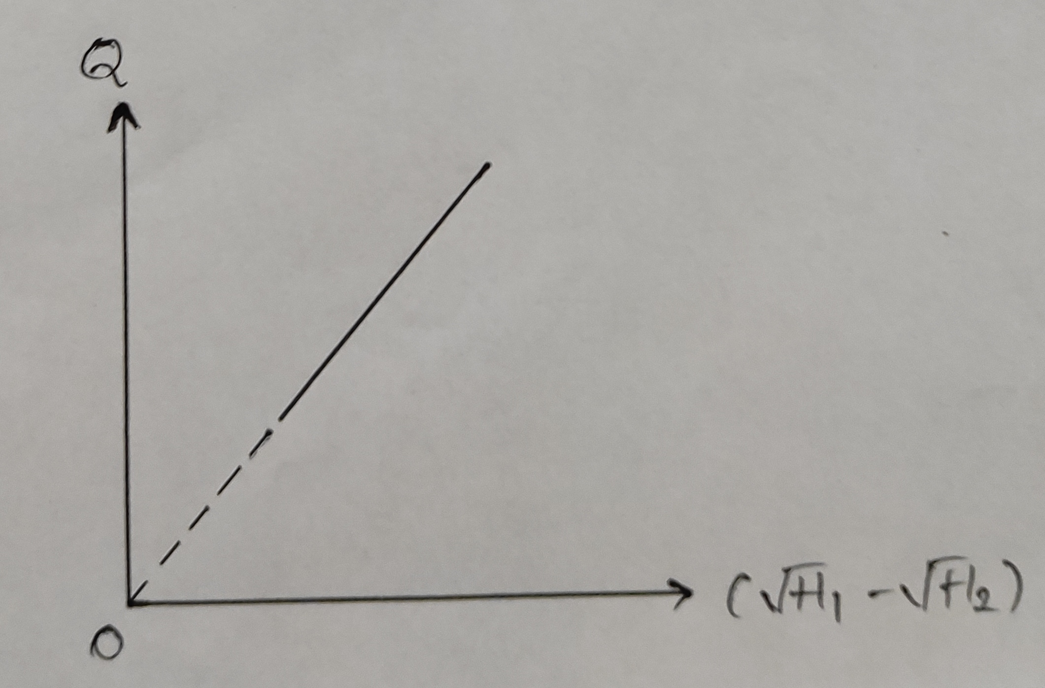
Precautions:
1. Apparatus should be in levelled condition.
2. Reading must be taken in steady or near by steady conditions. And it should be noted that water level in the inlet supply tank must be constant.
3. There should not be any air bubble in the piezometer.
4. Orifice must be free from dirt and kept clean.
Result:
1. Constant head method:
a) The experimental average value of Cd =
b) Cd from Q vs H graph =
c) Cd from Q vs `\sqrt{H}` graph =
d) Cd from log Q vs log H graph =
2. Falling head method:
a) The experimental average of Cd =
b) Cd from `\sqrt{H_{1}}- \sqrt{H_{2}}` vs t graph =