Aim:
To determine the coefficients of discharge Cd, velocity Cv and contraction Cc small orifice.
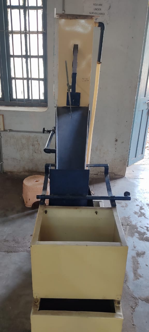
Experimental setup:
The experimental set-up consists of a supply tank with an overflow arrangement and a gauge glass tube for water level measurement in the tank. There is also provision for fixing the various orifices (interchangeable) installed in the vertical plane of the tank side. A set of orifices consisting of 10 mm and 15mm diameter orifices is provided with the apparatus. The arrangement is made such that the water passes only through this attached opening. Water comes out of the opening in the form of a jet.
A horizontal scale on which a vertical scale is mounted with a hook gauge is attached to the supply tank. Thus, hook gauge can be moved horizontally as well as vertically in the x and y directions and its corresponding movement can be read on the horizontal scale and vertical scale respectively. A collecting tank is used to determine the actual discharge of water through the jet.
Formulae:
1. Coefficent of velocity, `C_{v} = \frac{x}{2\sqrt{yh}}`
2. Coefficent of contraction, `C_{c} = \frac{C_{d} }{C_{v} }`
where,
x = Horizontal distance of fluid particle from the center of orfice in cm = x' - x0
y = Vertical distance of fluid particle from the center of orifice in cm = y' - yo
h = Reading on the piezometer at the level of center of orifice in cm
x' = Reading on the horizontal scale at a point along the trajectory of jet in cm
y' = Reading on the vertical scale at a point along the trajectory of jet in cm
Theory:
An orifice is an opening in the wall of a tank.Orifices are used for discharge measurement. The jet approaching the orifice continues to converge beyond the orifice till the streamlines become parallel. This section of the jet is then a section of minimum area and is known as vena contracta.
If Vc is the true horizontal velocity at the vena contracta, then the properties of jet trajectory give the following relationship: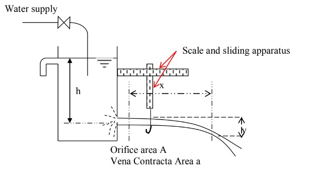
`V_{c}=\sqrt{\frac{gx^{2}}{2y}}`
The theoretical velocity in the plane of the vena contracta Vo is given by
`V_{o}=\sqrt{2gh}`
Now coefficient of velocity, Cv = Actual velocity / Theoritical velocity
`C_{v} = \frac{x}{2\sqrt{yh}}`
In which h is the constant head in the supply tank and x & y are coordinates of jet with respect to centre of opening.
The actual discharge Q when divided by a`\sqrt{2gh}` yield the coefficient of discharge Cd. Here a is the area of cross section of the orifice and g is the acceleration due to gravity.
Once Cd and Cv are known, the coefficient of contraction Cc can be obtained by dividing Cd with Cv,
`C_{c} = \frac{C_{d} }{C_{v} }`
The coefficient of discharge can be also be computed by falling head method in which the supply is kept closed after filling the tank to a suitable level and fall in the head from H1 to H2 in time t is noted. The coefficient of discharge is then obtained from
`C_{d} = \frac{2A(\sqrt{H_{1}}-\sqrt{H_{2}})}{t a \sqrt{2g}}`
Procedure:
1. Note down the relevant dimensions, such as the cross-sectional area of collecting tank and the supply tank.
2. Attach an orifice and note down its diameter.
3. The water supply was admitted to the supply tank, and conditions were allowed to steady to give a constant head. The lowest point of the orifice is used as the datum for the measurement of h and y.
4. The discharge flowing through the jet is recorded along with the water level in the supply tank.
5. A series of readings of dimensions x and y were taken along the trajectory of the jet.
6. The above procedure is repeated by means of a flow control valve.
Observations:
Diameter of the orifice, d = ..........cm
Reading on the piezometer at the level on centre of orifice, ho = ..........cm
Reading of horizontal scale at the exit of orifice, xo = ..........cm
Reading of vertical scale at the exit of the orifice, yo = .......... cm
Table:
| SNo. | h (cm) |
x' (cm) |
y' (cm) |
x (cm) |
y (cm) |
Cv |
|---|---|---|---|---|---|---|
| 1 | ||||||
| 2 | ||||||
| 3 | ||||||
| 4 | ||||||
| 5 |
Precautions:
1. Apparatus should be in levelled condition.
2. Reading must be taken in steady or near by steady conditions. And it should be noted that water level in the inlet supply tank must be constant.
3. There should not be any air bubble in the piezometer.
4. Orifice must be free from dirt and kept clean.
Result:
1. Coefficient of velocity of small orifice, Cv = ..........
2. Coefficient of contraction of small orifice, Cc = ..........
1. Coefficient of discharge of small orifice, Cd = ..........