Aim:
To determine coefficient of discharge of triangular notch and rectangular notch.
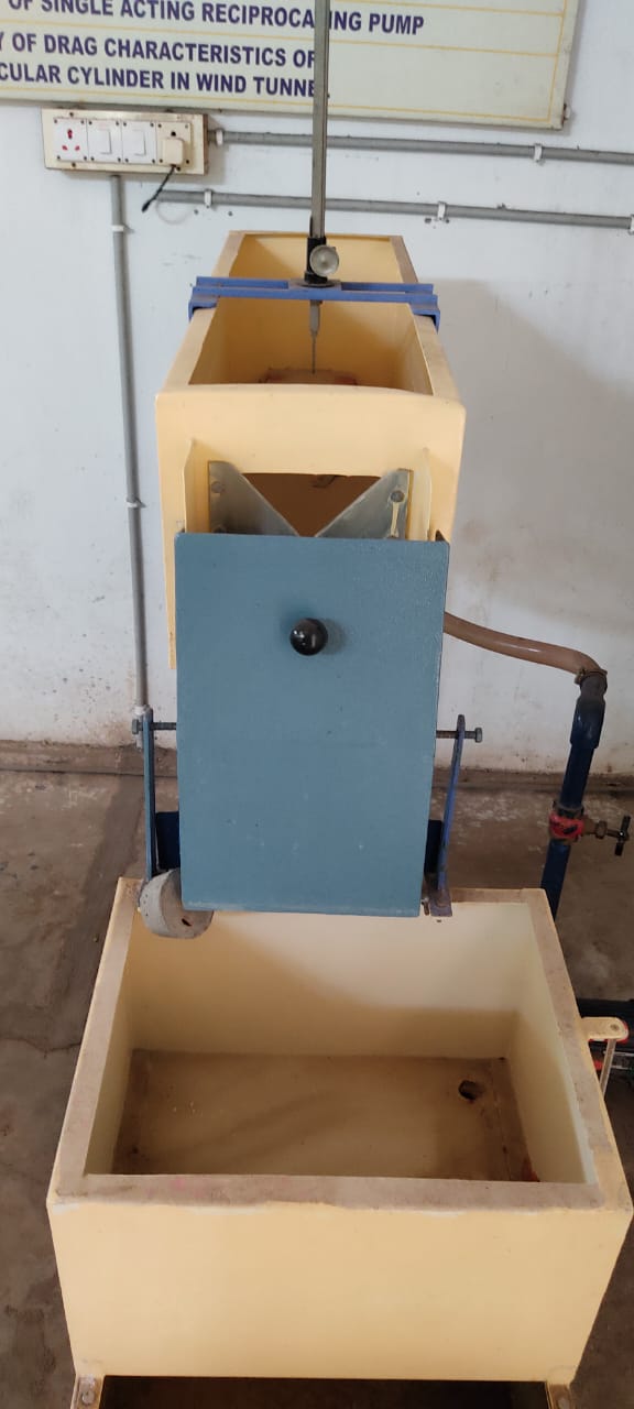
Experimental setup:
The experimental set up consists of a tank whose inlet section is provided with 2 nos. of baffles for streamline flow. While at the downstream portion of the tank one can fix a notch of either V or rectangular. A point gauge is used to measure the head of water over the model. A collecting tank is used to find the actual discharge through the notch.
Formulae:
1. Actual discharge, `Q_{act}=\frac{AR}{T}` cm3/sec
2. Theoritical discharge,
a) `Q_{th}=\frac{8}{15}\sqrt{2g}H^{\frac{5}{2}}\tan\frac{\theta}{2}` cm3/sec (for triangular notch)
b) `Q_{th}=\frac{2}{3}\sqrt{2g}BH^{\frac{3}{2}}` cm3/sec (for rectangular notch)
3. Coefficient of discharge, `C_{d}=\frac{Q_{act}}{Q_{th}}`
where,
A = Cross sectional area of the collecting tank in cm2
R = Rise in the level of water in collecting tank in cm
T = Time taken for R cm rise in collecting tank
g = Acceleration due to gravity = 980 cm/sec2
B = width of rectangular notch in cm
θ = Apex angle of triangular notch in degrees
H = Head over the notch in cm = H2 - H1
H1 = crest level of notch above the channel in cm
H2 = Depth of flow of water in the channel in cm
Theory:
Different types of models are available to find discharge in an open channel as notch, venturiflume, weir etc. For calibration of rectangular notch or V notch some flow is allowed in the flume. Once the flow becomes steady, uniform discharge coefficients can be determined for any model.
In general, sharp crested notches are preferred where highly accurate dischargemeasurements are required. For example in hydraulic laboratories, industry andirrigation pilot schemes, which do not carry debris and sediments.
Notches are those overflow structures whose length of crest in the direction of flow is accurately shaped. They may be rectangular, trapezoidal, V notch etc. The V- notch is one of the most precise discharge-measuring device suitable for a wide range of flow. Making the following assumptions as to the flow behaviour can develop the relationship between discharge and head over the weir:
(a) Upstream of the weir, the flow is uniform and the pressure varies with depth according to the hydrostatic equation P = ρgh
(b) The free surface remains horizontal as far as the plane of the weir, and all particles passing over the weir move horizontally.
(c) The pressure through out the sheet of liquid or nappe, which passes over the crest of the weir, is atmospheric.
(d) The effect of viscosity and surface tension are negligible.(e) The velocity in the approach channel is negligible.
A triangular or V notch is having a triangular or V shaped opening provided in its body so that water is discharged through this opening only. The line which bisects the angle of the notch should be vertical and at the same distance from both side of the channel. The discharge coefficient Cd of a V notch may be determined by applying formula.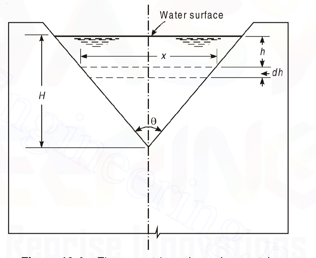
`C_{d}=\frac{Q}{\frac{8}{15}\sqrt{2g}H^{\frac{5}{2}}\tan\frac{\theta}{2}}`
Where,
Q is the discharge over a triangular notch
θ is the apex angle of notch
H isthe head over the crest of the notch.
A rectangular notch, symmetrically located in a vertical thin plate, which is placed perpendicular to sides and bottom of a straight channel, is defined as rectangular sharp-crested weir. The discharge coefficient Cd of a rectangular notch may be determined by applying formula
`C_{d}=\frac{Q}{\frac{2}{3}\sqrt{2g}BH^{\frac{3}{2}}`}`
Where,
Q is the discharge over a rectangular notch
B is the width of notch
H is thehead over the crest of the notch
g is acceleration due to gravity.
Procedure:
1. The notch under test was positioned at the end of the tank, in a vertical plane, and withthe sharp edge on the upstream side.
2. The tank was filled with water up to the crest level and subsequently note down the crest level of the notch by the help of a point gauge.
3. The flow-regulating valve was adjusted to give the maximum possible discharge without flooding the notch.
4. Conditions were allowed to steady before the rate of discharge and head H were recorded.
5. The flow rate is reduced in stages and the readings of discharge and H were taken.
6. The above procedure is repeated for other type of notches.
Observations:
Area of collecting tank, A = .......... cm2
Rise in level of water in collecting tank, R =.......... cm
Width of notch, B = .......... cm (Rectangular notch)
Apex angle, θ = ..........° (Triangular notch)
Table: (same for both notches)
| SNo. |
H1 (cm) |
H2 (cm) |
H (cm) |
T (sec) |
Qact (cm3/sec) |
Qth (cm3/sec) |
Cd |
|---|---|---|---|---|---|---|---|
| 1 | |||||||
| 2 | |||||||
| 3 | |||||||
| 4 | |||||||
| 5 |
Graphs:
1. Q Vs H: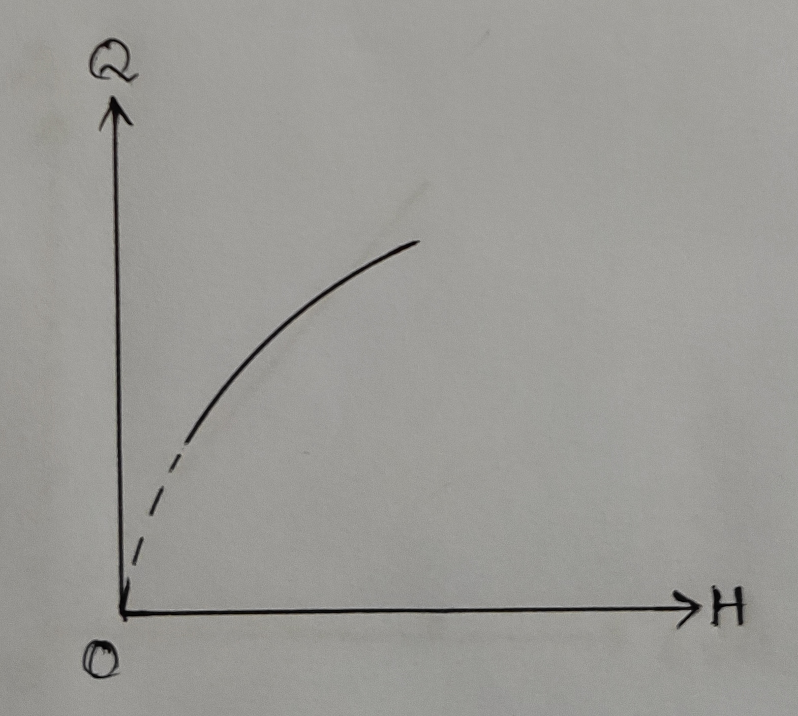
2. Log Q Vs log H: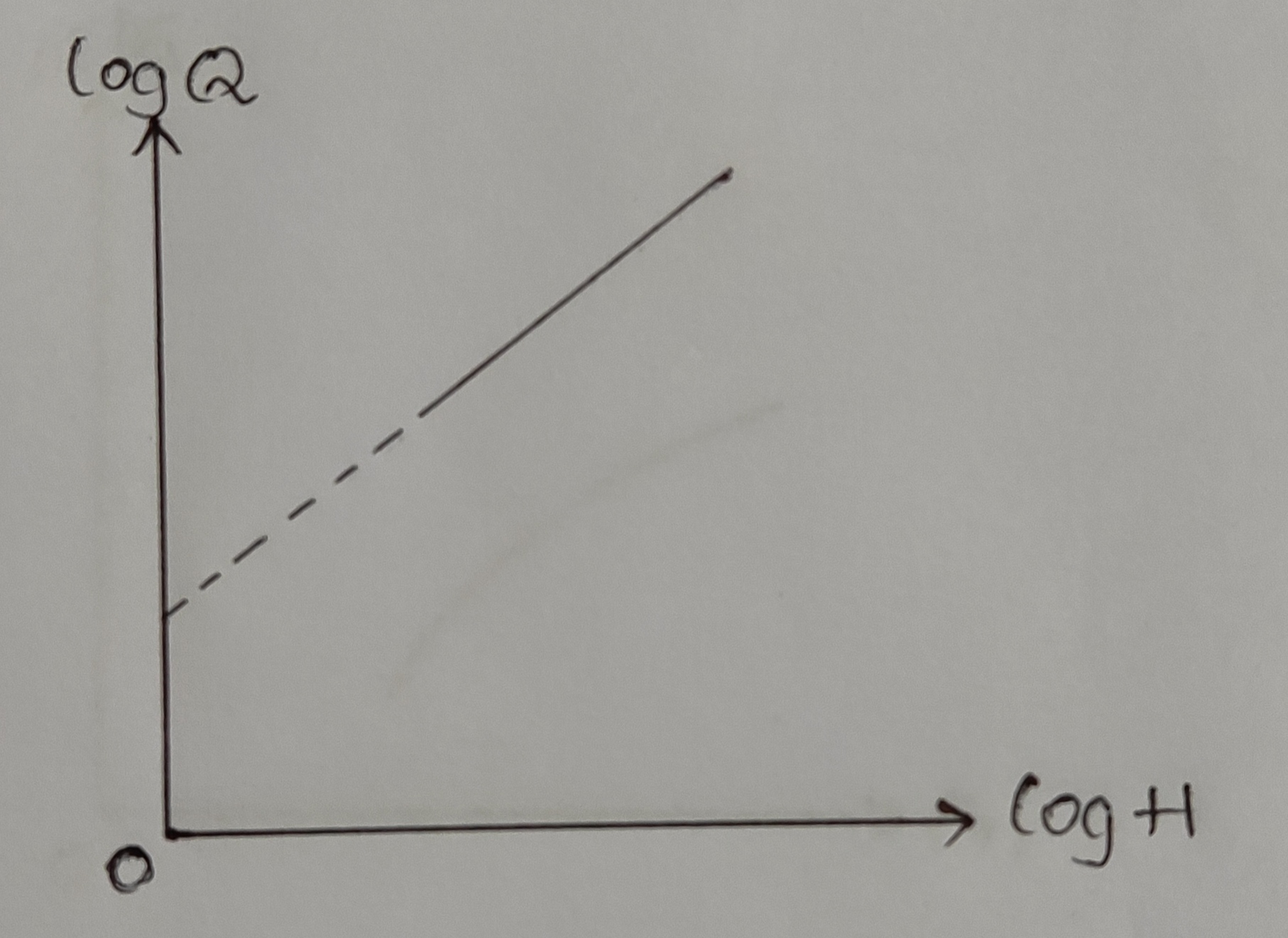
3. Q vs `\sqrt{H}`: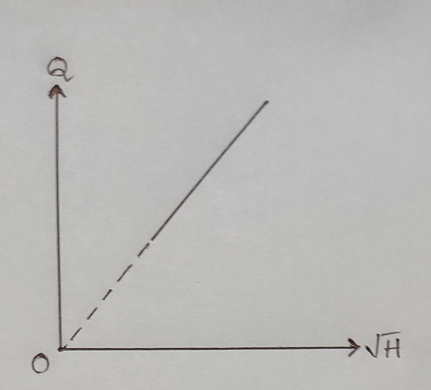
Precautions:
1. Reading must be taken in steady or near steady conditions.
2. For the measurement of correct discharge there must not be any leakage near the notch and take care that notch is not running in overflow conditions.
3. For measurement of correct head over the notch the point gauge must be installed little distance away from the crest of the notch.
4. Discharge must be varied very gradually from a higher value to smaller values.
Result:
1. Coefficient of discharge of triangular notch,
a) From average of calculated values, Cd = ..........
b) From Qact Vs H graph, Cd = ..........
c) From Qact Vs `\sqrt{H}` graph, Cd = ..........
d) From log Qact Vs log H graph, Cd = ..........
2. Coefficient of discharge of rectangular notch,
a) From average of calculated values, Cd = ..........
b) From Qact Vs H graph, Cd = ..........
c) From Qact Vs `\sqrt{H}` graph, Cd = ..........
d) From log Qact Vs log H graph, Cd = ..........